Motor Technology
- Share

Brushless Motor Technology | OEM/ODM Manufacturing
Brushless Motor Technology and Manufacturing Process
Jinwa develops DC and AC brushless motor solutions through a controlled path from specification review and stator winding to permanent-magnet rotor assembly, electronic commutation, balancing, end-of-line testing and traceability.
- DC and AC brushless architectures
- Controlled production checkpoints
- Model-specific test planning
- OEM/ODM engineering review
Controlled from input to release
Brushless Motor Manufacturing Process
Our process framework connects the electrical design, mechanical construction, drive electronics and quality records required for repeatable brushless motor production. The exact in-house, approved-supplier and model-dependent scope is confirmed for each program.
-
 01
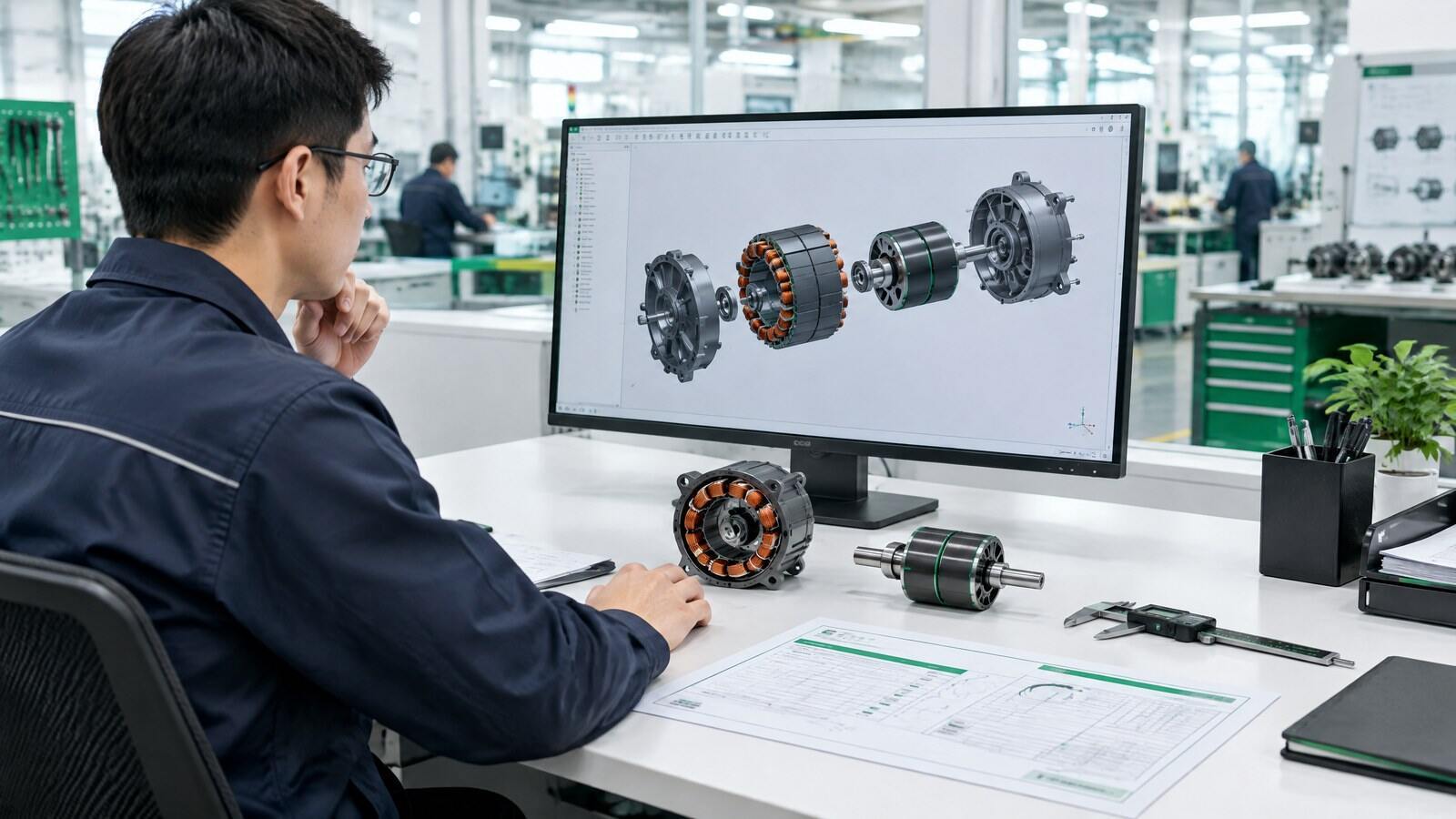
01Product Definition and Quality Planning
We review input architecture, voltage, speed, torque or load profile, dimensions, shaft and mounting interfaces, control method, environment and duty cycle before sample release.
Control point: approved specification, risk review and revision status -
 02
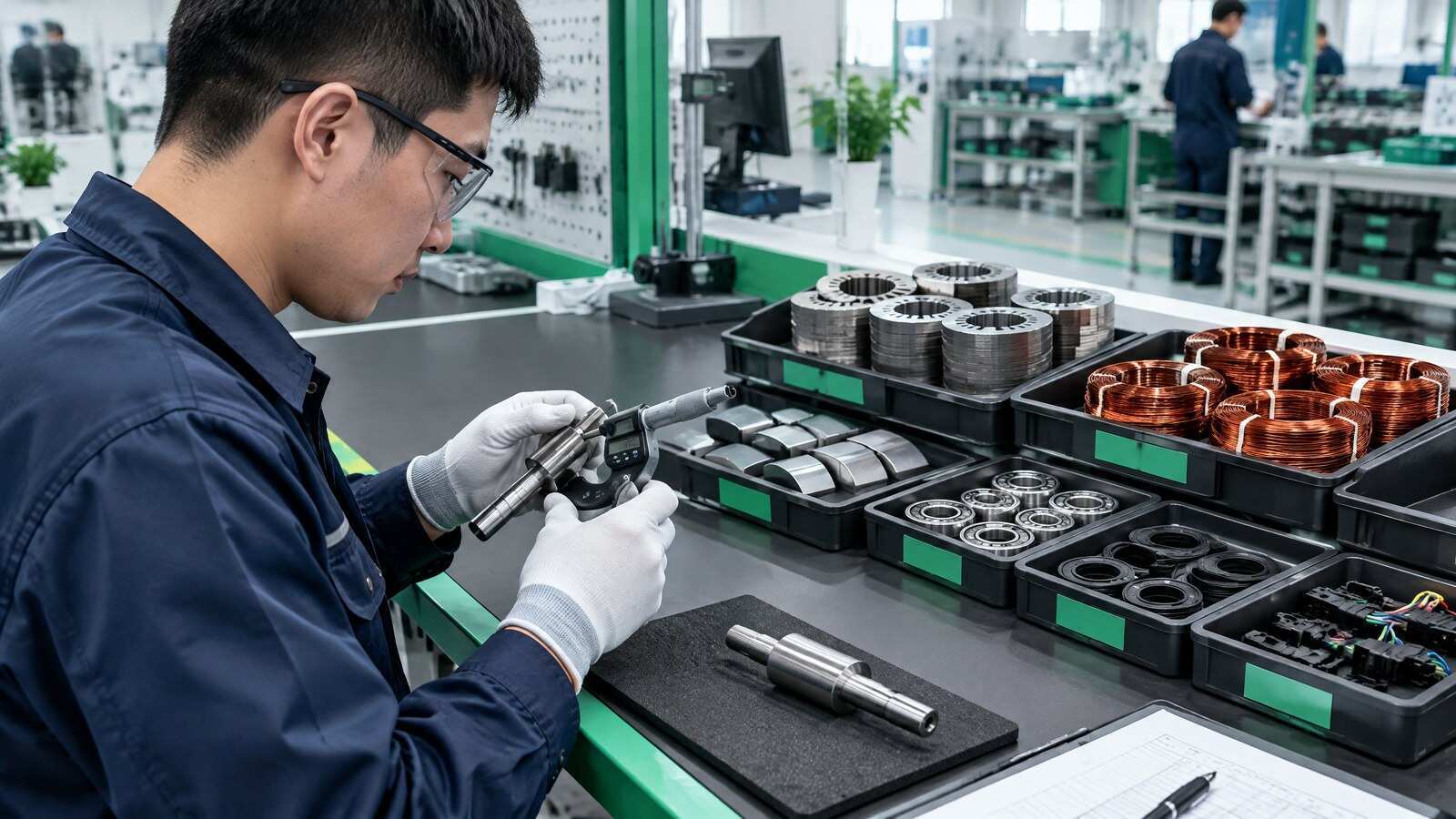
02Material Identification and Incoming Inspection
Electrical steel, copper wire, insulation, magnets, shafts, bearings, seals, connectors, PCBA components and molding materials are identified against the applicable bill of materials and inspection plan.
Control point: supplier lot, inspection result and material disposition -
 03
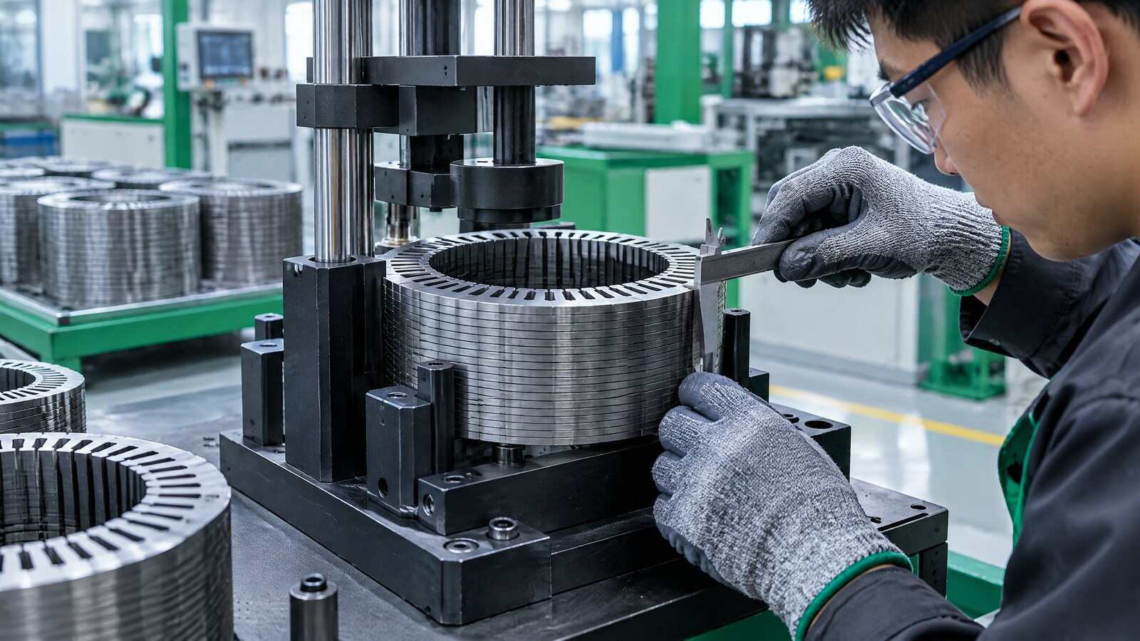
03Stator Core Stamping and Stacking
Lamination profile, burrs, coating, stack length, locating features, end faces and interlaminar insulation are controlled to support the specified magnetic and mechanical design.
Control point: lamination profile, burr, stack and insulation integrity -
 04
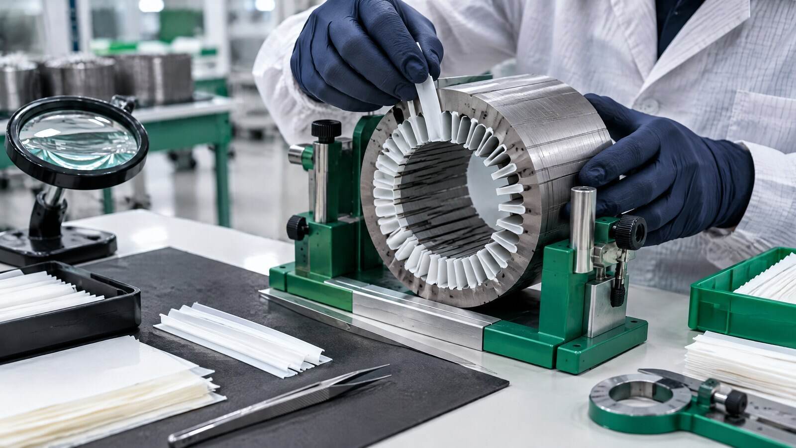
04Slot Insulation and Winding Preparation
Slot liners and insulation components are prepared for the specified wire, voltage, thermal system and winding layout. Placement, coverage and damage are checked before winding.
Control point: insulation coverage, slot condition and wire specification -
 05
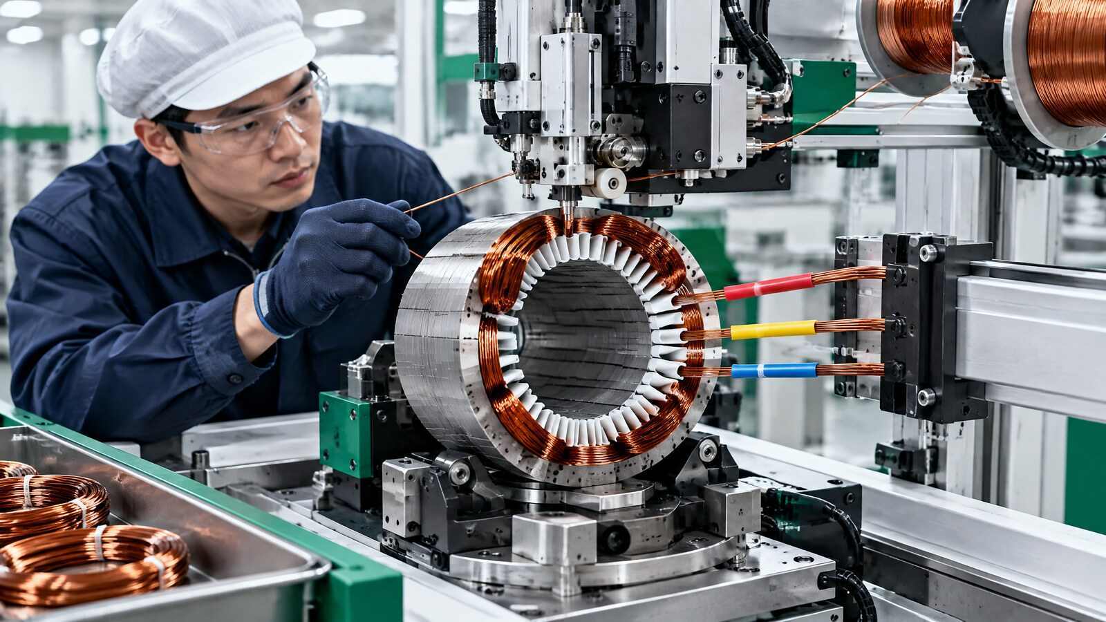
05Winding, Insertion and Phase Connection
Wire diameter, turns, parallel conductors, slot position, phase sequence, tension, end-turn height, enamel condition and terminal connection are controlled for the approved winding design.
Control point: turns, phase sequence, resistance and terminal integrity -
 06
06Varnish, Potting and Insulation Consolidation
The approved insulation method is applied according to the motor design. Material identity, coverage, voids, process condition, cure profile and sealing boundaries are recorded where applicable.
Control point: material lot, process condition, cure and coverage -
 07
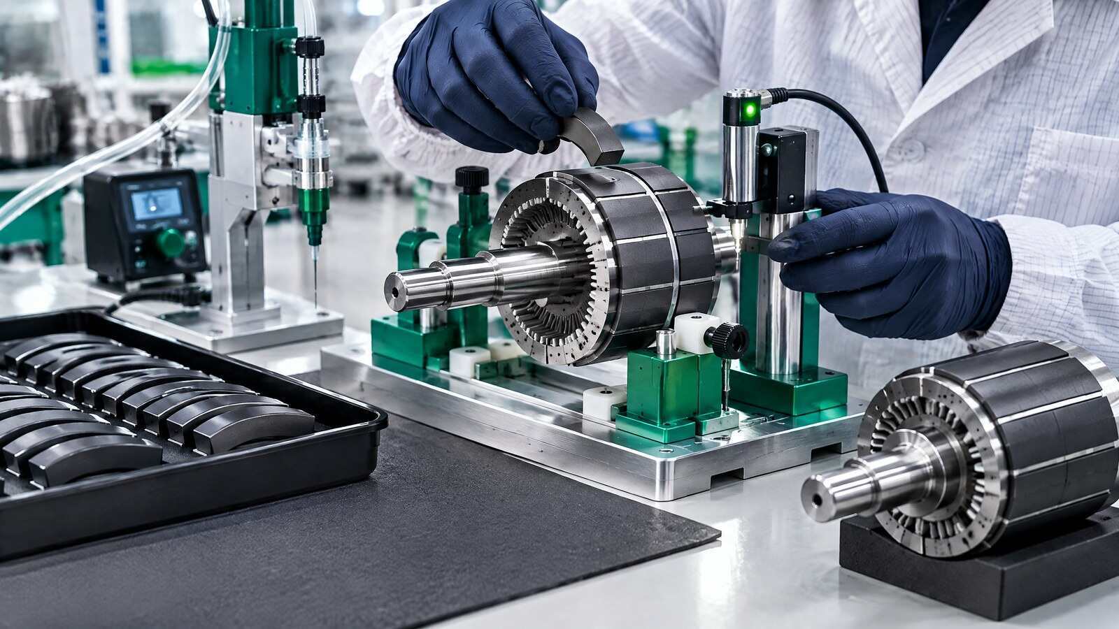
07Permanent-Magnet Rotor Assembly
Magnet batch, dimensions, polarity, magnetic condition, position, adhesive application, curing and the model-specific retention method are checked before the rotor is released for balancing.
Control point: polarity, placement, bonding and retention -
 08
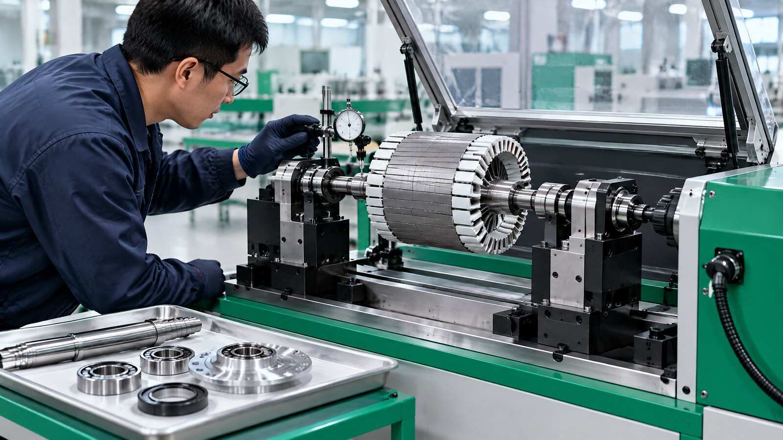
08Dynamic Balancing and Shaft-System Assembly
The rotor state, correction planes, balancing condition and acceptance criterion are defined by model. Shaft, bearings, end covers, seals, runout, end play and alignment are then verified.
Control point: balance result, runout, end play and alignment -
 09
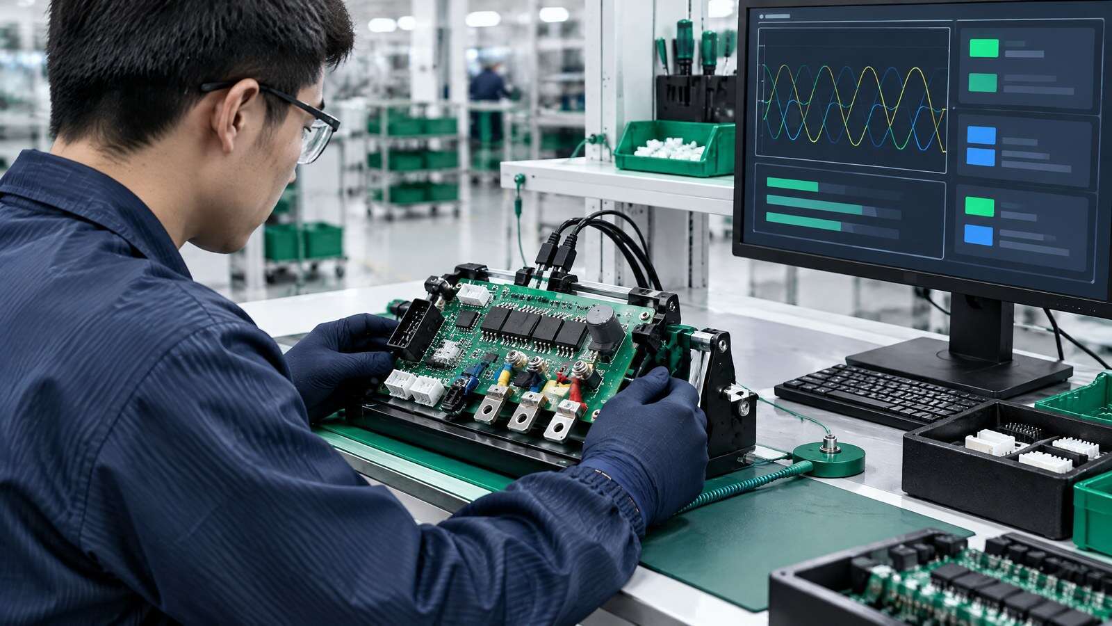
09Controller, PCBA and Firmware Control
For integrated or matched drive systems, component identity, solder quality, connector keying, firmware revision, parameter set, calibration and protection behavior are controlled by configuration.
Control point: PCBA lot, firmware revision, parameters and calibration -
 10
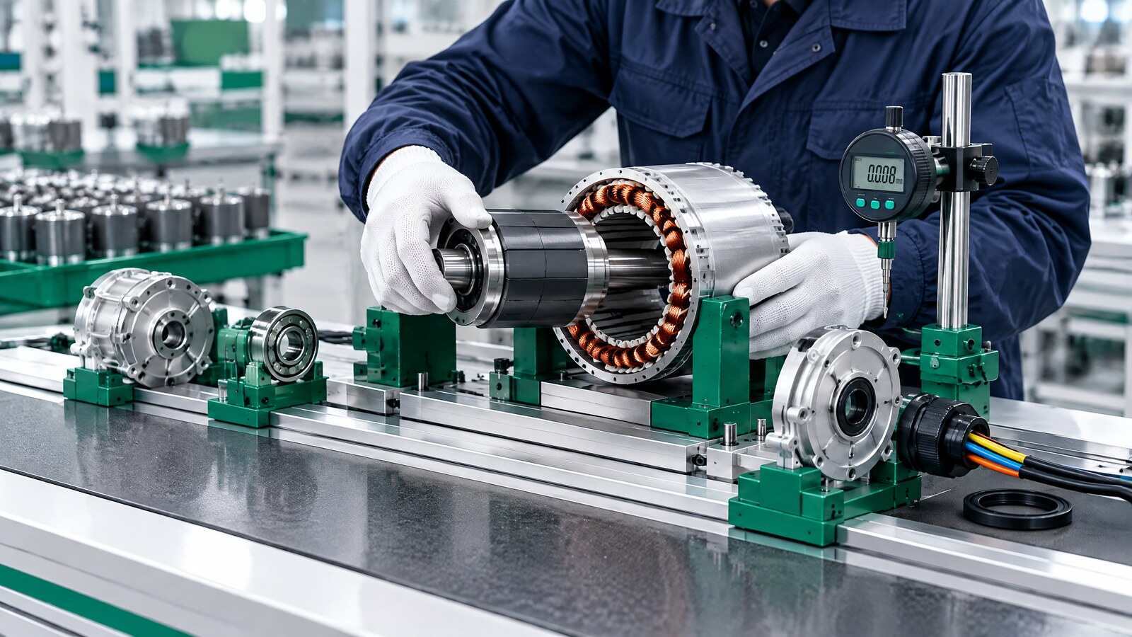
10Motor Assembly and Interface Verification
Stator, rotor, housing, shaft system, seals, cable or connector and customer interfaces are assembled with checks for fit, air gap, concentricity, cable exit and mechanical dimensions.
Control point: interfaces, air gap, concentricity and sealing boundaries -
 11
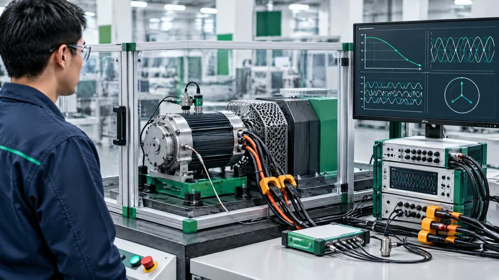
11Electrical and Performance Testing
A model-specific matrix may include phase resistance, insulation, dielectric withstand, surge, back-EMF, no-load and load operation, speed, current, vibration, noise, temperature rise and protection checks.
Control point: measured result against the approved model limit -
 12
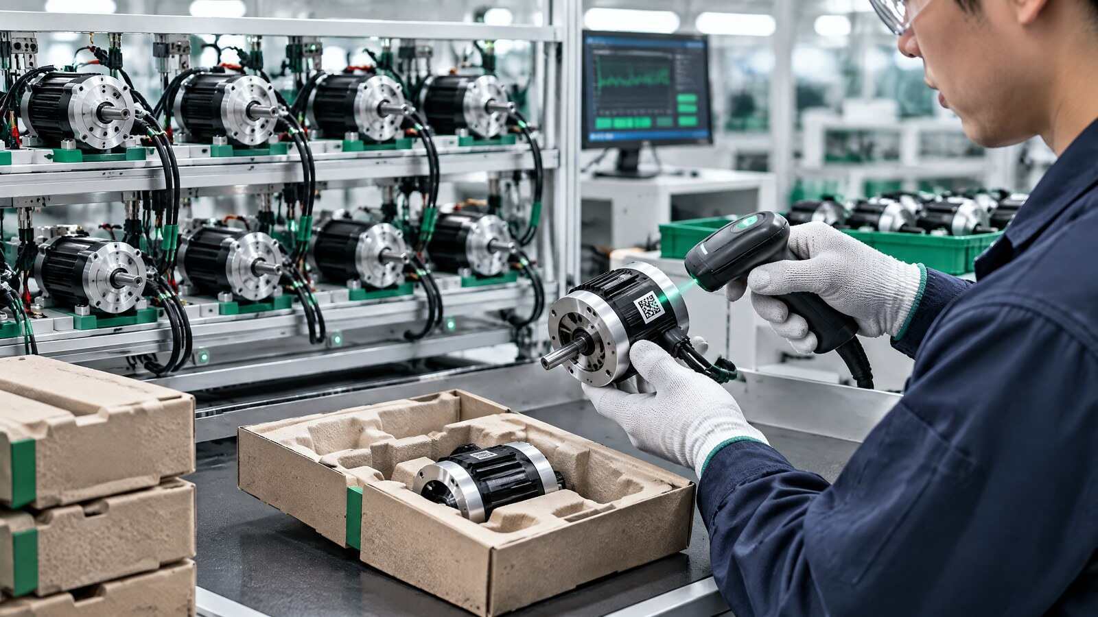
12Aging, Release, Packaging and Traceability
Where required by the program, aging or endurance screening precedes final release. Serial records can connect critical material lots, controller configuration, calibration and end-of-line results.
Control point: serial number and approved production history
Architecture terminology
DC and AC Brushless Motor Platforms
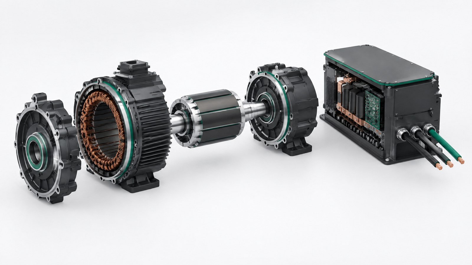
"Brushless motor" describes a motor-and-drive system rather than one universal electrical interface. B2B specifications should identify the input stage, winding and back-EMF design, commutation method, feedback method and controller boundary.
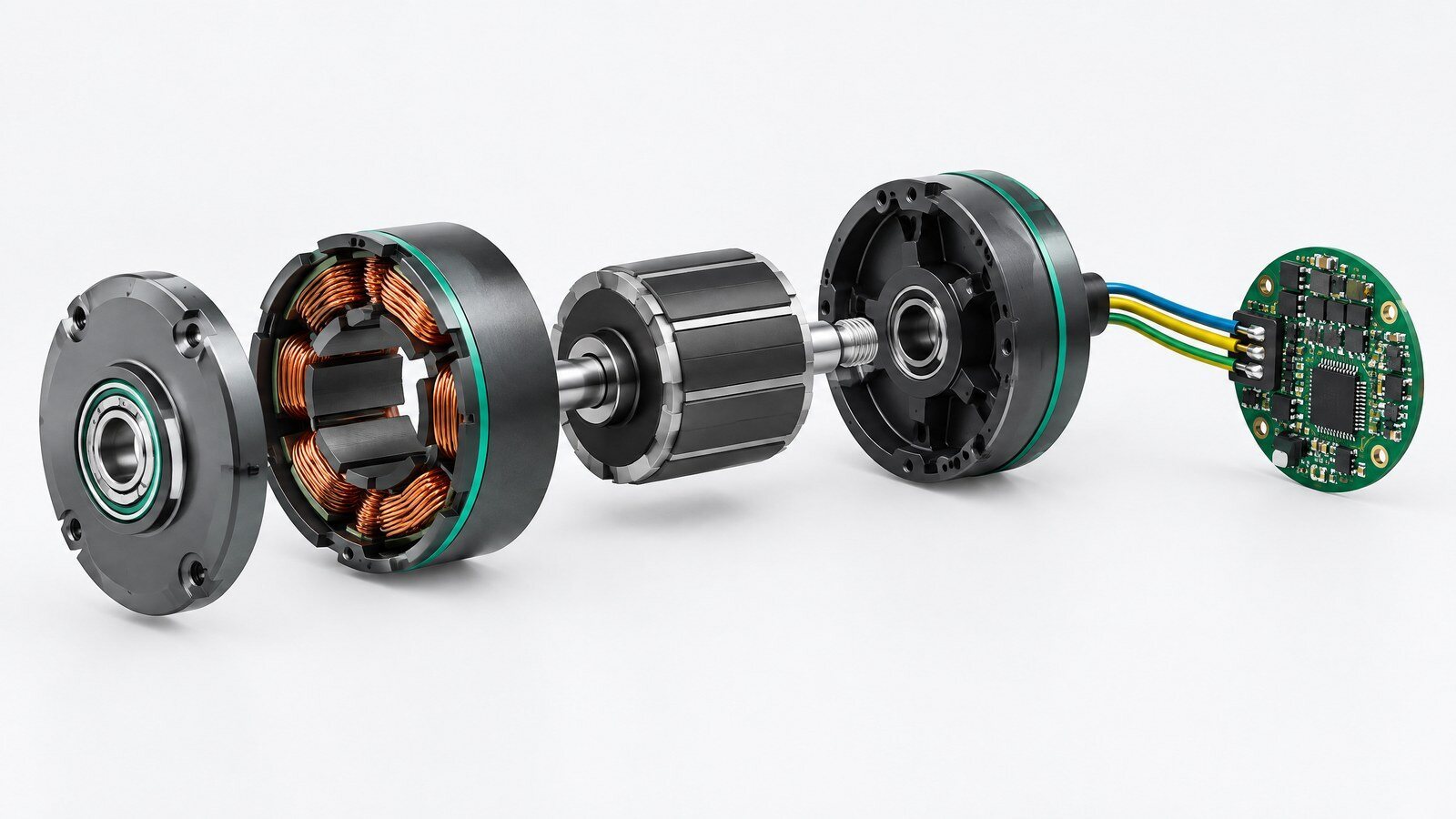
DC Brushless Motor (BLDC)
A DC source or DC bus supplies an electronic inverter that creates controlled phase currents in the stator. BLDC systems may use Hall feedback, sensorless estimation or another position method.
- Confirm nominal and allowable DC input range.
- Define six-step, sinusoidal or other commutation at model level.
- Specify startup, speed control and protection requirements.
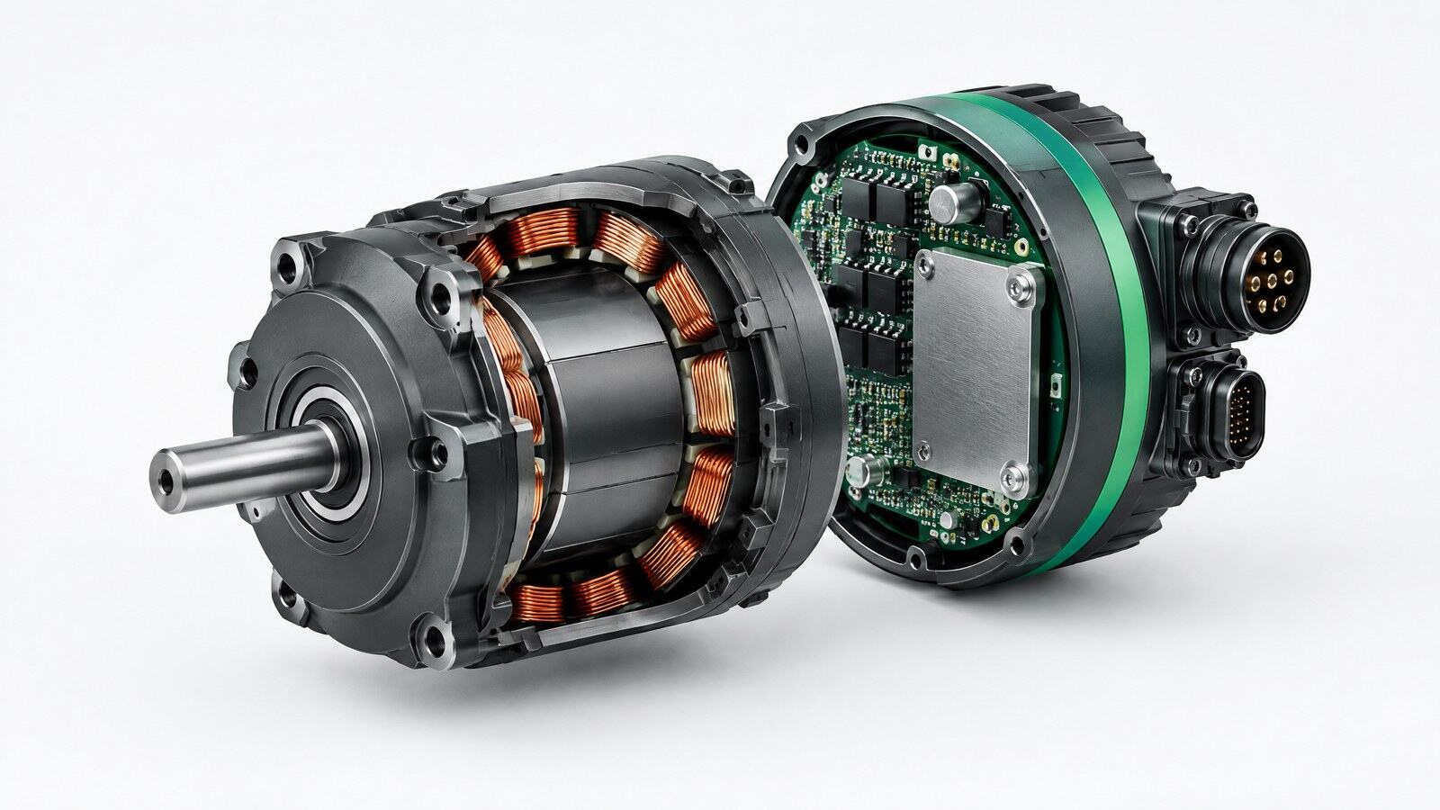
AC Brushless Motor (PMSM / BLAC)
AC brushless terminology commonly covers permanent-magnet synchronous architectures with electronically generated phase currents. An AC-input product may include rectification and inversion, or the motor may use an external drive.
- Confirm AC input, DC-link and isolation boundaries.
- Define sinusoidal control, FOC or the approved drive method.
- Separate motor, controller and complete-system performance.
EC Motor and Integrated Drive
EC means electronically commutated motor. In different markets, the term may overlap with BLDC or PMSM systems and may indicate integrated electronics. The exact topology must be stated in the product specification.
- Confirm whether the controller is integrated, separate or customer-owned.
- Define command, feedback, communication and fault interfaces.
- Verify thermal, electrical-safety and environmental boundaries.
B2B project support
Support for Brushless Motor Development and Supply Qualification
The commercial page should present a clear engineering and evidence workflow rather than unsupported performance claims.
Engineering Requirement Review
- Input voltage and architecture
- Speed, torque or load profile
- Dimensions, shaft, mounting and interfaces
Quality and Test Planning
- Incoming and in-process checkpoints
- Electrical, thermal and NVH test matrix
- Model-specific acceptance data

OEM/ODM and Documentation Support
- Drawing and revision coordination
- Sample, validation and production planning
- Traceability and change communication
Send Your Brushless Motor Requirements for Engineering Review
Tell us whether your project uses a DC bus, an AC input or an external drive. Include voltage, speed, torque or load, dimensions, control and feedback, operating environment, sample target and estimated annual volume.
Recommended attachments: motor drawing, existing datasheet, load curve, interface definition or acceptance checklist.